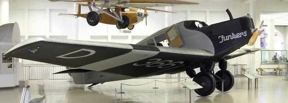
Cantilever Monoplanes
Part of the DNA of the modern airliner can be found in the four-passenger Junkers F.13, a low-wing cantilever monoplane which was clad in corrugated metal skin. First flying in 1919, the Hugo Junkers-designed aircraft was an instant step beyond its wood-and-fabric biplane contemporaries, and highly durable. The skin, made from an aluminum alloy called Duralumin, was partially stressed and helped the wing spars carry shear loads. The success of the F.13 paved the way for other metal-skinned early airliners developed by Fokker and the William Stout-designed Ford Trimotor, which took to the air in 1926.
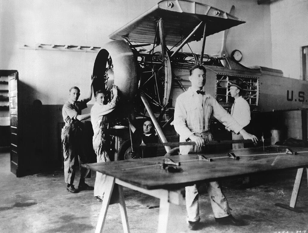
Engine Cooling Drag
Relatively little attention was paid to reducing airframe drag until the mid-1920s when work at the National Advisory Committee for Aeronautics (NACA, forerunner to NASA) led by Fred Weick, head of Langley’s new 20-ft.-dia. Propeller Research Tunnel, focused on reducing the high drag of radial engines. Weick’s work, paralleled to some degree by studies at the National Physical Laboratory in the U.K., led to the low-drag engine cowling which improved cooling and cut drag by two-thirds.
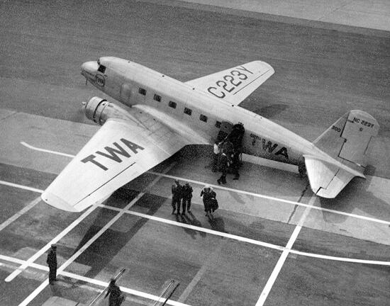
Streamlining and Stressed Skin
While early metal skins provided torsion and shear loads, stressed skin also absorbed bending loads. Developed theoretically by Herbert Wagner in Germany in the late 1920s, the first practical stressed-skin wing structure was independently devised and constructed by Jack Northrop for his X-216H flying wing. By riveting stringers to the inside surface of the wings, the loads could be shared with the spars. Similarly, fuselage ribs and skins could be integrated into stressed, shell constructions which were stronger, yet lighter, and enabled aerodynamically cleaner designs. Boeing’s all-metal Model 247, which first flew in 1933, integrated stressed skins, retractable gear and advanced features such as an early autopilot, trim tabs and deicing boots. In response, Douglas Aircraft developed the stressed-skin DC-1, progenitor of the DC-2 and DC-3.
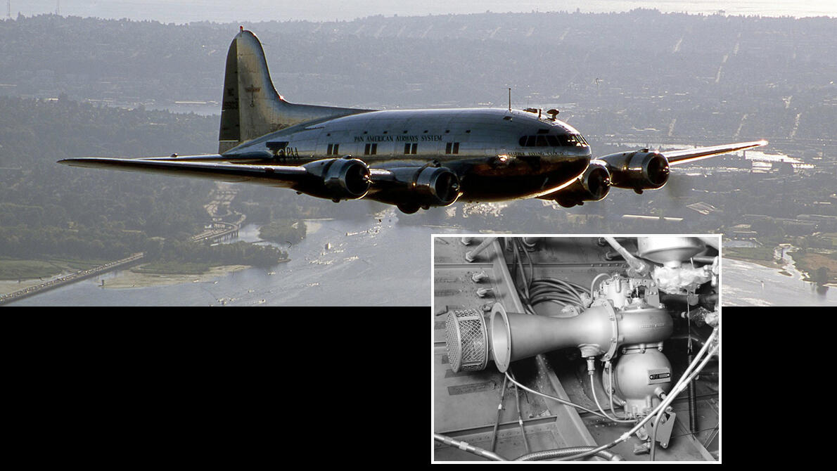
Pressurization
In the mid-1930s, U.S. airlines grew increasingly interested in the potential development of larger, pressurized, four-engine airliners. TWA launched its own “over-the-weather” research program with the modified DC-1 and later a Northrop “Gamma” testbed fitted with oxygen for the crew and supercharged engines. Boeing developed the pressurized Model 307 Stratoliner, which married the Model 299 (B-17) wings, tail and landing gear with an all-new semi-monocoque fuselage with a circular cross-section. The pressurization system used air from General Electric Type B-1 superchargers fitted to the aircraft’s Wright Cyclone engines, and a breakthrough regulator to maintain constant cabin pressurization levels.
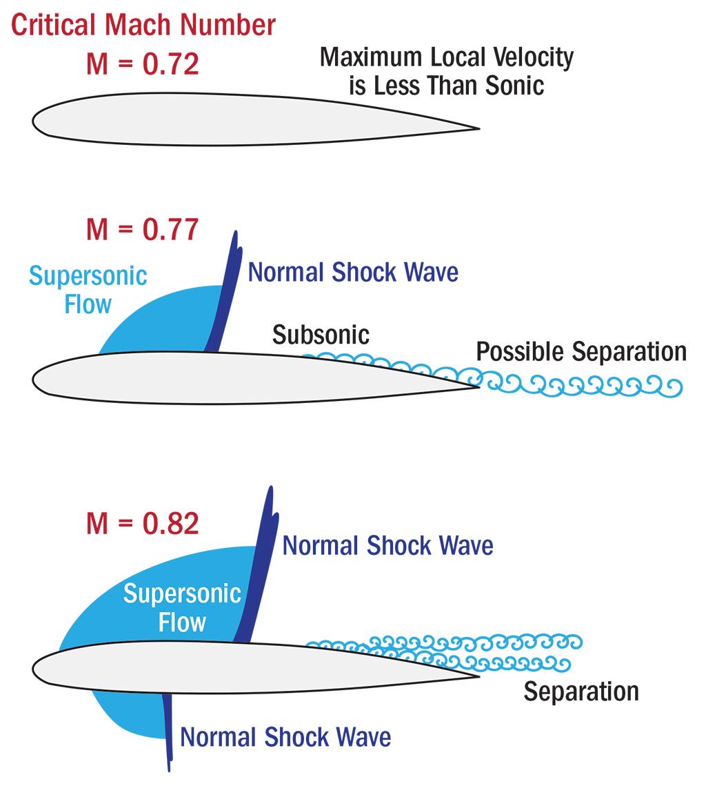
Compressibility
As more powerful fighter aircraft were developed during World War II, pilots began to encounter compressibility effects at high speeds. The problems increased as the aircraft neared the speed of sound, a speed ratio dubbed the “Mach” number in honor of the 19th-century gas dynamics physicist Ernst Mach. Dealing with the issue became imperative as speed increased with the introduction of jet-powered airliners. Problems encountered as the aircraft reached a critical Mach number (close to the speed of sound, or transonic) included “Mach tuck,” in which the aircraft nose would pitch down as the center of lift moved aft, as well as buffeting and reduced elevator effectiveness. To address these concerns, designers introduced several new features including an all-moving trimming tail, thinner, reduced camber airfoil sections and swept wings.
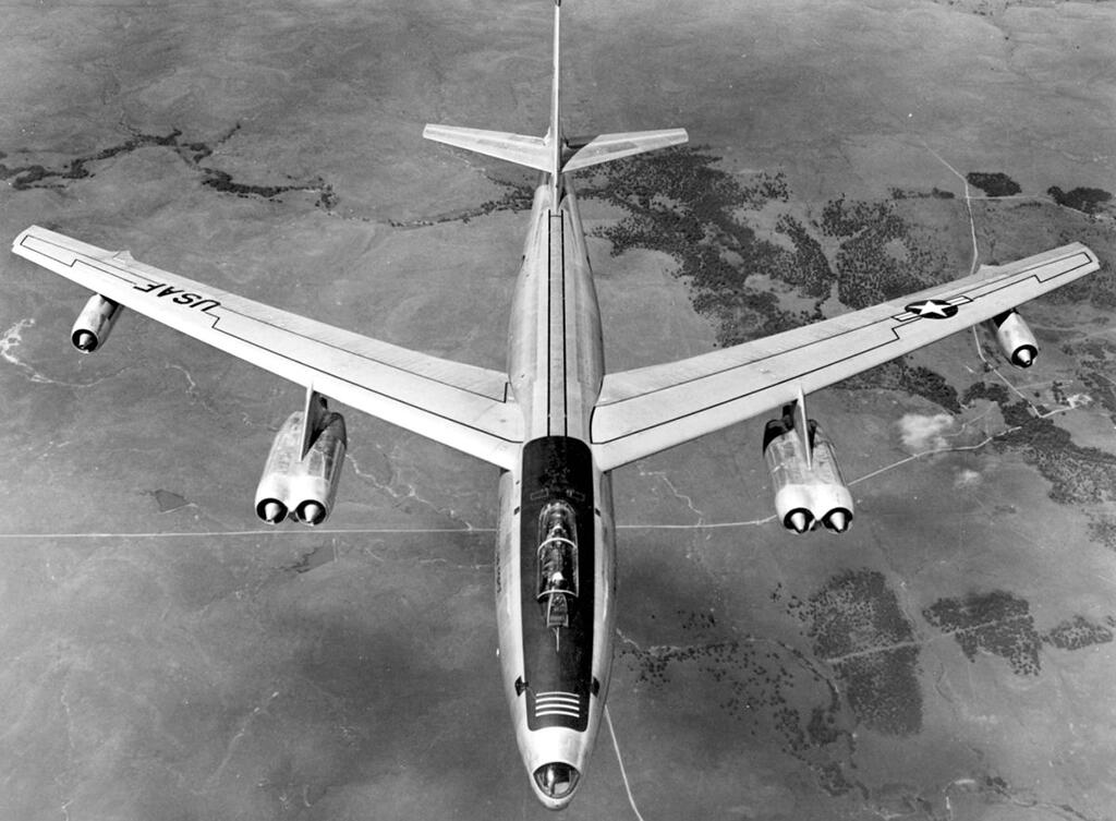
Sweep Back
Wing sweepback allows jet airliners to cruise at high subsonic speed because it delays the shock waves and drag rise associated with the onset of compressibility effects. German aircraft such as the Me-163 and Me-262 appeared with modest leading edge sweepback in the Second World War, mostly for stability reasons rather than drag reduction. Germany’s breakthrough high-speed aeronautical research was subsequently seized on by Boeing for the design of its B-47 jet bomber. The aircraft’s swept wings and pod-mounted engines provided the template for the majority of airliner configurations developed over the past six decades.
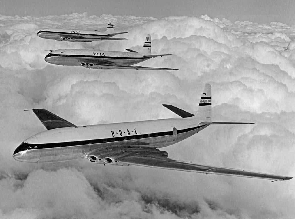
Fatigue Life and Fail Safe
The combination of higher operating altitudes and pressure cabins brought about a dramatic increase in operating cycles; it also meant that early jet airliner manufacturers were unwittingly entering unknown territory when it came to airframe fatigue. This was revealed to the industry through a string of catastrophic inflight breakups in 1953 and 1954 involving the de Havilland Comet 1, the first jet-powered airliner to enter service. Stress concentrations around the windows fatigued the materials around small rivet holes, causing the explosive development of a crack several feet long. The Comet accidents led to the adoption of fail-safe design for airliners, which mandates multiple load paths to maintain structural strength in the presence of a crack or damage. Later changes additionally required that airliner structures must also be damage tolerant.
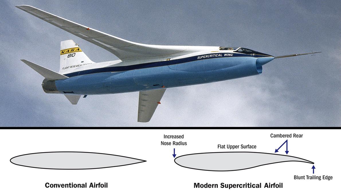
Supercritical Wings
While early jet airliners relied on wing designs with conventional cross-sections, aerodynamicists including Richard Whitcomb at NASA Langley and Dietrich Kuchemann at RAE Farnborough realized more performance could be gained by tailoring the airfoil for transonic conditions. The focus was on delaying the onset of the supersonic shock wave over the wing which causes wave drag, thereby allowing more efficient cruise performance at a higher Mach number. The resulting airfoil cross-sections were much flatter on the upper surface, blunter at the nose and inversely cambered at the lower aft wing surface. The flatter upper surface helped maintain a smoother boundary layer, while the blunt leading edge attenuated the suction peak and the scooped-out lower aft surface provided aft loading to generate increased lift. The overall outcome was that the shock wave moved further aft over the wing and reduced in intensity.
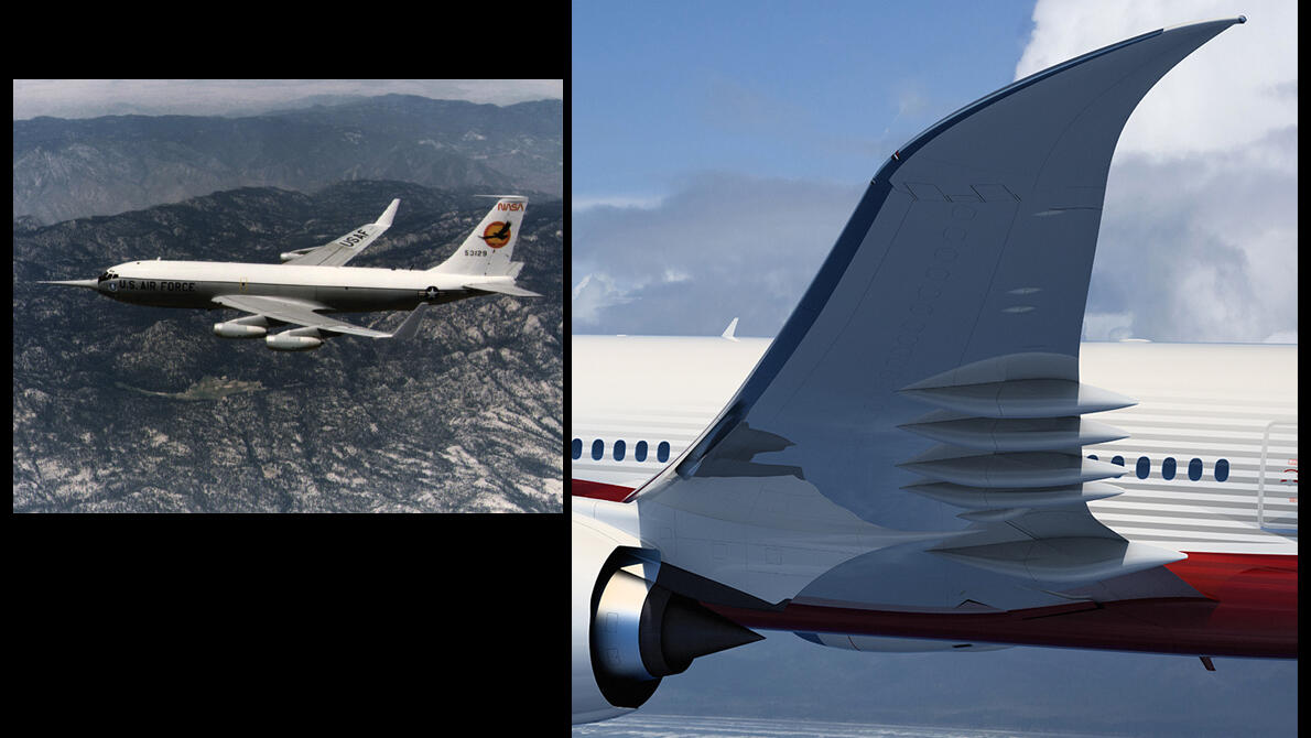
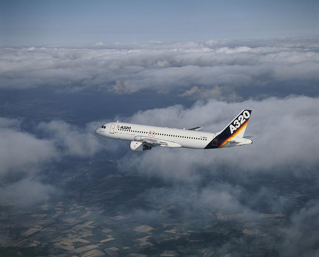
Winglets
Another aerodynamic improvement feature, now widespread across the modern airliner fleet, is the drag-reducing winglet. The winglet reduces vortex-induced drag by diffusing the tip vortex flow downstream of the wingtip and, in addition, increases lift at the wingtip by inhibiting the flow of higher-pressure air below the wing to lower-pressure air above. Developed initially in response to the 1973 oil crisis, NASA flight-tested a Whitcomb-designed winglet on a Boeing KC-135 in 1979, but it was not until 1988 that a similar-looking feature debuted on the 747-400. Airbus meanwhile adopted a lower-profile end-plate wingtip device which projected above and below the end of the wing. The shape was first introduced on the A310-300 and A320 and, in a much larger form, on the A380. McDonnell Douglas also tested a form of bifurcated winglet on a DC-10 in 1981 and introduced a 7-ft.-tall upper winglet with lower vane on the MD-11 in 1990. Larger elliptical or blended winglets are now commonplace on Airbus and Boeing aircraft, although all-new wing designs on the 787, 747-8, 777 and 777X feature raked tips.
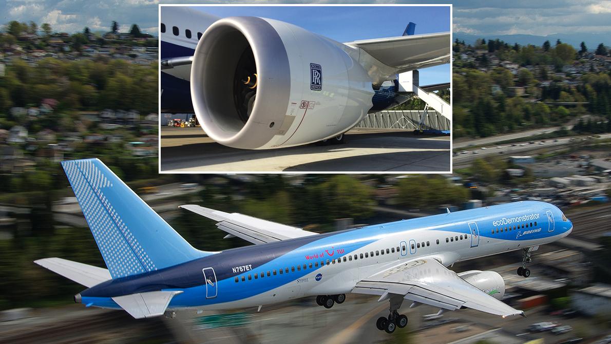
Laminar Flow
By maximizing the amount of smooth, uninterrupted “laminar” airflow over the aircraft’s skin, designers hope to reduce skin friction as well as delay the onset of drag-generating turbulent flow. Experiments to control laminar flow, either passively, actively or with a hybrid system combining both approaches, were conducted in the U.S. and Europe. There are two main methods for achieving laminar flow: passively, by retaining a smooth surface profile and keeping it clean from dirt and insects; or actively, by removing the boundary layer via sucking it into the wing leading edge through very small holes. Boeing has developed a natural laminar flow nacelle for the 787 and recently tested a laminar flow wing section as part of the 757 ecoDemonstrator tests.
Power-assisted Controls
As airliners increased in size and complexity, the traditional methods of balancing control-surface forces with set-back hinges, horn balances and aerodynamic balance tabs, were no longer sufficient. Hydraulically boosted controls were tried out by Douglas for its experimental DC-4E but were rejected in favor of conventional aerodynamic-balanced controls in the production DC-4. The competing Boeing 307 would instead emerge as the first airliner to have hydraulically boosted elevators and rudder. Later generations incorporated fully powered control systems with redundancy provided in the form of split-control surfaces, each powered by its own actuator, power source and control system. These systems have also been adapted to include maneuver and gust load-alleviation devices.
Fly-by-Wire
Fully integrated load alleviation has been made easier by the increasing use of fly-by-wire flight control systems. Flight controls are electrically signaled from the cockpit controls instead of being mechanically connected by cables. As well as reducing weight and complexity, the system can be programed to keep pilots within the aircraft’s flight envelope. It also provides improved handling characteristics, lightening pilot workload.
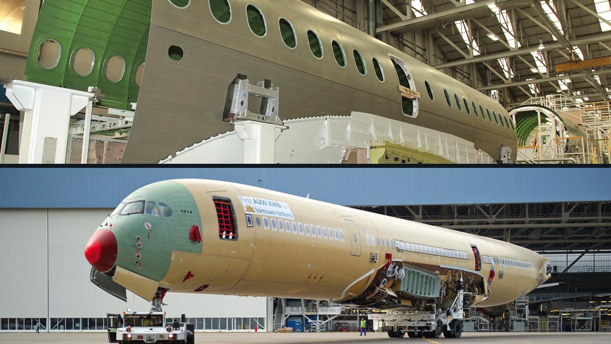
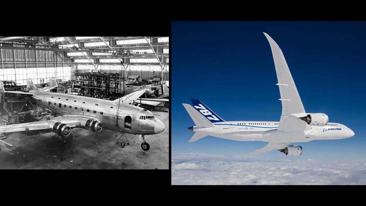
Advanced Alloys and Composites
From the mid-1980s onward, there has been a steady increase in the use of non-metallic fiber-reinforced plastics such as carbon-fiber reinforced polymer (CFRP) composites. A series of new heat-treated alloys and lighter-weight aluminum-lithium alloys have been developed to counter the composite challenge, the latter weighing around 10% less than the widely used 2000 series alloys used in various forms for aircraft since the 1920s, while retaining the same strength as the 7000 series. Despite positive stiffness, fatigue and corrosion properties, the use of Al-Li has been limited, largely due to high lithium production costs. The material was, however, selected by Bombardier for the fuselage skins of the C Series; for future single-aisle designs Al-Li is expected to be cost competitive with composites. A hybrid material incorporating fiber and aluminum, called Glare, was selected by Airbus for the fatigue-critical upper-fuselage skin sections of the A380. Composites are now increasingly used in primary structures; they form 50% of the 787 airframe and 53% of the A350’s.
The speed, range, safety and altitude capability of airliners improved dramatically over the past century, thanks to a series of key technology breakthroughs in structures, aerodynamics, propulsion and systems. These advances accelerated the airline industry on the course toward the global economic engine that it is today. Though by no means meant to be comprehensive, we list some of the most significant as part of a series of special Centennial editions to mark the 100th anniversary of Aviation Week & Space Technology:
100 Years Of Commercial Airliner Technology
How Commercial Aircraft Shapes And Sizes Evolved
This gallery was originally published on October 23, 2015.