
NASA, Hamilton Standard/Allison Propfan
Type: Puller, single-stage swept-blade propfan
Rotor diameter: 9 ft.
Thrust: 9,000 lb.
The design roots of the newly unveiled open fan reach back to the mid-1970s when, as part of a national response to the 1973 oil crisis, NASA established the Advanced Turboprop project to extend the low-speed propulsive efficiency of the propeller to higher subsonic speeds. Key to the concept were radically new highly swept, thin blades designed by Hamilton Standard that mitigated compressibility effects. In wind-tunnel tests, the scimitar-like blades indicated potential fuel savings of more than 20% for medium-range airliners cruising at Mach 0.8.

Dubbed a “propfan” for greater public perception, the design was mounted on an Allison 501 turboprop and flown in a puller—or tractor—configuration on a Gulfstream II in 1987 under the Propfan Test Assessment program.

General Electric GE36
Type: Pusher, contrarotating direct-drive unducted fan
Rotor diameter: 11 ft. (aft rotor)
Thrust: 25,000 lb.
Prompted by another wave of rising fuel prices in the early 1980s, General Electric meanwhile took the concept a step further with the GE36 unducted fan (UDF)—an engine with a propulsor similar to the propfan—but driven by a modified turbofan rather than a turboprop. The design, which is also known as an open rotor, was a pusher with two rows of blades spinning in opposite directions to reduce swirl losses and produce a near-axial exit flow. The GE36 with eight blades on each row flew on a Boeing 727-100 testbed in 1986-87, followed by two further test efforts on a McDonnell Douglas MD-80 in 1987-88. The second of these tested the UDF engine with 10 blades in the front row and eight aft.

The GE36 rotors were directly driven by the turbine via contrarotating, statorless turbine stages. While this effectively doubled the turbine’s rpm, enabling the turbine to be smaller and more efficient, it also resulted in a complex mechanical arrangement. The front-stage fan was driven by turbine blades attached to the inside of the outer case, while the aft fan was driven by blades attached to the shaft. Thermal and load imbalance issues drove the requirement for lightweight composite fan blades—a technology later exploited for the first time on the GE90.

P&W Allison 578-DX
Type: Pusher, contrarotating geared unducted fan
Rotor diameter: 11 ft. 7 in. (aft rotor)
Thrust: 22,000 lb.
Hamilton Standard and Allison also teamed with Pratt & Whitney to develop the 578-DX pusher open-rotor engine with two rows of contrarotating blades. Unlike the direct-drive GE36, the 578-DX incorporated a 13:1 reduction gearbox between the low-pressure turbine and the fan blades. Flight tests of the 578-DX, which incorporated six blades on each row, took place on an MD-80 in 1989.

Interest in open rotors revived in the 2000s amid rising fuel prices with research programs in the U.S. and Europe focusing on noise, vibration, thermal management and airframe integration. Using modern computer-based design methods, NASA, the FAA and GE collaborated in 2009-12 on scaled aeroacoustic tests of a GE36-derived blade design.

NASA analyzed the flow and interaction effects of a contrarotating, open rotor using a computational fluid dynamics solver. In this image red particles are seeded on the upstream blades, blue on the aft blades. As well as improved blade geometry, NASA and GE testing also built on other noise-mitigation lessons learned in the 1980s, including increased blade counts, reduced disk loading, increased spacing between rotors and between pylon and rotor, and clipping the aft rotors to reduce tip vortex interaction.

European tests within the Clean Sky aeronautics research program culminated in the Safran-led counter-rotating open rotor (CROR) project. Initial supporting work included aeroacoustic testing of advanced low-noise blade designs and tonal interaction between blade sets in a pusher configuration.

Safran SAGE 2 Open Rotor
Type: Pusher, contrarotating geared unducted fan
Rotor diameter: 13.1 ft. (front rotor)
Thrust: 22,000 lb.
CROR tests concluded in 2017 under the SAGE 2 (Sustainable and Green Engines) project. The open-rotor pusher design consisted of two contrarotating stages powered by a gas generator from the M88 combat engine.

CFM Open Fan
Type: Puller, geared open-rotor active stator
Rotor diameter: 12-13-ft. range
Thrust: 25,000-30,000-lb. range
GE Aviation and Safran’s Open Fan configuration is a puller design with a single stage of rotating blades and a second stage of active variable-pitch stators. To be tested under CFM’s Revolutionary Innovation for Sustainable Engines (RISE) program, the engine will include a compact core, new low-emission combustors, heat exchangers and motor-generators for hybrid-electric systems.

Future open-rotor designs will be highly integrated with airframes and require development of new certification standards for critical areas such as protection of the fuselage from potential blade impact. Joint work between the FAA, the European Union Aviation Safety Agency and NASA to determine the certification base for open rotors in the 2010s included testing of a protective shield structure against blade release using a full-scale rig at the Naval Air Weapons Station in China Lake, California.
Open rotors are not a new idea. Since the earliest research and development began in the 1970s, the concept has gradually evolved toward a viable propulsion system capable of simultaneously meeting modern noise requirements and double-digit fuel-burn performance targets. Aviation Week reviews some of the key milestones along the long and sometimes bumpy road leading to CFM’s recently announced open-fan next-generation engine demonstrator initiative.
Comments
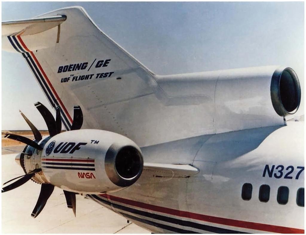
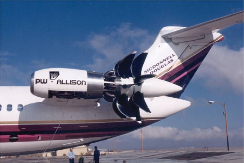
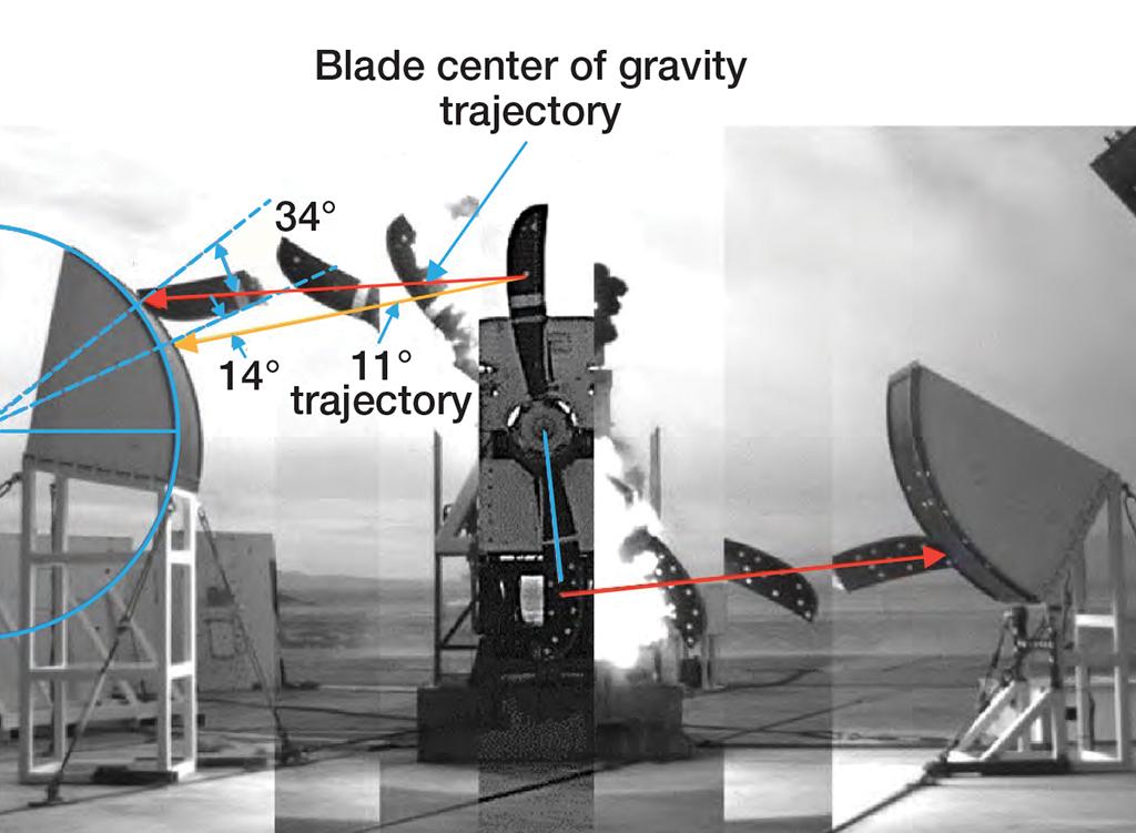
The picture for the 'General Electric GE36' segment shows quite substantial armor on the vertical tail, the center inlet duct, and the tail cone above and below the pylon. Does anyone remember the material and thickness of that armor?